2017年3月31日星期五

Practical Application of Fiber Enclosure

As part of overall cable-management system, fiber enclosure is used in a wide range of interconnect facility applications, from data centers to building backbone, horizontal, and entrance facilities to provide high density and safe cabling environment. Generally, there are two types of fiber enclosure often deployed in data centers: rack mount and wall mount fiber enclosure. Wall mount enclosure is for cable connecting between floor and floor, while rack mount enclosure is for cabling connecting between or within racks. Today, we’re going to talk about how to deploy these two fiber enclosure types in data center.

Fiber Enclosure Overview
Wall mount enclosure, as its name indicates, is usually installed on the wall for housing and distribution of fiber optic cables for indoor application, while rack mount enclosure is often used between or within racks. Wall mount enclosure and rack mount enclosure are often loaded with fiber adapter panels (LC, SC, or MPO fiber adapter panel are commonly used) and slack spools or sometimes with MPO LC cassette. Take the wall mount enclosure in FS.COM as an example, it is often loaded with 2, 4, 8 fiber adapter panels and 2 slack spools which can provide easy-to-manage environment for fiber patch cords. Besides, it can also be loaded with 2, 4, 8 MPO cassettes as shown below for maximum density in limited space while reducing installation time.

wall-mount-fiber-enclosure

How Can We Apply Fiber Enclosure?
As more and more cabling used in data center, cable management becomes vital. Poor patch-cord management has proven to limit cool air getting to outside ports on networking equipment, which causes early failure. Fiber optic enclosure is a good way to support cable running and managing. The following image shows the fiber enclosure application in multi-floor data center.

fiber-enclosure-in-multi-floor-application

As the picture shows, the rack mount enclosure loaded with MPO cassettes and wall mount enclosure holding MPO fiber adapter panel are used to manage MPO patch cable or standard LC fiber cable in high density data center. The fiber adapter panel serves as the intermediate connection between multi-floor data center backbone and patching cabling, while the MPO cassette can provide the connection between 40/100G and 10G devices. The MPO cassette in the rack mount enclosure can also be replaced by MPO adapter panel for direct trunk cable to fan-out interface. No matter how you run cables in the data center, you will always route and manage the fiber cables with flexible move, add and cut(MACs) with the help of fiber enclosure.

Conclusion
As IT managers are more prone to high density data center, it is time to use fiber enclosure for easy-managing your fiber optic cables. All the components we have mentioned above, including MPO cassette, MPO fiber adapter panel, MPO fiber cable, wall mount and rack mount fiber enclosure can be purchased in FS.COM. If you’re interested in, kindly visit FS.COM.
2017年3月30日星期四

What Should We Prepare for 40/100G Migration?

As data center of all types continue to grow in terms of traffic and size, 40G and 100G Ethernet technology is no longer a pipe dream—it is well on the way and set to become the new standard for high bandwidth and intelligent architecture. Faced with this upcoming trend in data center, what preparation should we do? Read this post, and you will get some details.
LC or MPO Interfaced 40/100G Modules?
Normally, there are two interfaces that 40/100G transceivers use: LC and MPO. LC interfaced modules will be used over single-mode fiber for long distance data transmission, while MPO interfaced modules are commonly deployed with multimode fiber for short distance. However, there are also some transceivers not following this rule. For example, 40GBase-UNIV uses duplex LC connector, but it only supports 150 meters over OM3 or OM4 fiber, and 500 meters over single-mode fiber as we have mentioned in the previous post. Besides, 100GBase-PSM4 is a single-mode module, but it has MPO interface to achieve data transmission. Choosing LC or MPO interfaced 40/100G transceiver totally relies on the transmission distance that your practical application requires.
TypeFiber and DistanceConnector
40GBase-SR4100m(OM3) 150m(OM4)MPO(male/female)
40GBase-LR410km(SMF)Duplex LC
40GBase-UNIV150m(OM3) 150m(OM4) 500m(SMF)Duplex LC
100GBase-SR4100m(OM3) 150m(OM4)MPO (male/female)
100GBase-LR410km(SMF)Duplex LC
100GBase-PSM4500m(SMF)MPO (male/female)
Keep Budgets Down with Pre-terminated Cabling System
Cost is always the most important factor that every IT managers and ordinary users will concern. Since the technology for 40G and 100G is not as mature as 10G, devices used in these high-speed networks are more expensive, so we should keep our budget down as possible as we can in every aspect in the process of 40/100G migration. Then pre-terminated cabling system is a good choice.
pre-terminated assemblies for 40/100G
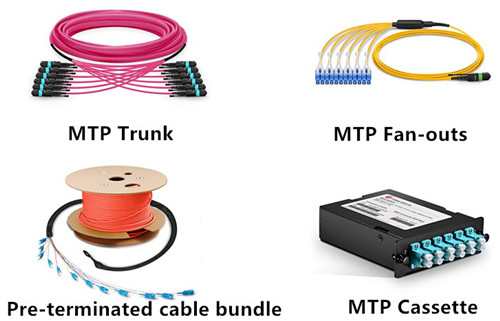
Pre-terminated cabling system contains factory manufactured cables and modular components with connectors already attached. It comes in a number of different forms, from connectorized fan-outs and attached or discreet cassette modules to cable bundles utilizing both fiber and copper with protective pulling grips installed over the connectors at one end. With these pre-terminated cabling, the need for labor to make terminations on site will be mitigated. And fewer labor means more savings on the labor bill. As report indicates, using the pre-terminated approach can achieve a saving of 57 percent.
Punch Down Solution  Pre-terminated Cabling
Material Cost             1X           3.2X
Labor Cost             2X           1X
Total             1X           1.3X
Installation Time             10 Hrs           5 Hrs
Future-Proof Your Network with 24-Fiber Infrastructure
In many 40/100G cases, 12-fiber system is more recommended to use between core switched and the equipment distribution area in the data center, but actually, if you want to future-proof your network, try 24-fiber infrastructure. Why? Let’s have a quick comparison.
For typically 40GbE applications, the 4 right and 4 left fibers of a 12 fiber MPO connector are used for transmit and receive while the inner 4 fibers are left unused. For 24-fiber 40GbE application, all fibers are utilized in the MPO plug. 24 fibers, divided by the 8 fibers per circuit that are required, yields 3 full 40GbE connectors. For 100GbE applications, if we choose 12-fiber MPO connector, we need two connector and two MPO trunk cables, the middle 20 fibers are used for transmit and receive 10Gb/s while the 2 fibers on the right are left unused. However, in this case, we just need one MPO 24 connector and one 24f trunk cable. As data centers continue to be crowded with more cabling, with 24-fiber system, about 1-1/2 times more pathway space could be saved.
24 fiber system for 40/100G
Conclusion
With the rapid increase in bandwidth consumption, the migration from 10GbE to 40/100GbE is inevitable. Proper interfaced transceiver, pre-terminated cabling system and 24-fiber infrastructure are required to build a cost-effective and high density 40/100G data center. If you’re interested in the components that we have mentioned above, kindly visit FS.COM.

2017年3月28日星期二

Patch Panel Plays a Role in High Density Cable Management

In a structured data center cabling, patch panel is a functional unit which can increase efficiency and the usefulness of the such a cabling. Without it, the transmission of data is rendered ineffectively, it consolidates all the horizontal cabling in any piece of infrastructure, allowing IT managers to terminate long and troublesome cables so that a signal is connected directly through a patch code to its destination. This post aims to introduce patch panel in the following text.

What More Benefits We Can Get from Patch Panel
Patch panel is a device which enables cable connections, usually involving a short cable plugged in the front and a long cable into the back of the patch panel. The primary advantage of using patch panel is improved organization and easier management of your network. It also serves as the nerve center for the cabling network. Simply put, the patch panel is where all the horizontal cabling in the infrastructure is consolidated. Besides, patch panel plays a central role in the administration of the telecommunications network by enabling the process of moves, adds and changes (MACs) in complex spaces. For example, if two workers must transfer desk locations, a simple switch of patch cords into various ports on a patch panel can ease the move. Without this capability, much time and energy would be spent termination cable that would have to be hard-wired. Here shows Cat5e patch panel.

cat5e-patch-panel

Patch panel is so critical to a system that if anything goes wrong with them, the entire system may fail, so it makes sense to choose patch panels carefully.

Copper VS. Fiber Patch Panel
Generally, there are copper and fiber patch panel available on the market. Some professionals are adamant that there is no real differences in the performance and construction, while others see a drastic differential between the copper and fiber products.

Cost: Cost is always the key consideration that most IT managers will concern. Commonly, the cost of fiber patch panel which having improved over the past year is far more than the copper equivalent. Such explains that the cost of actual installation is compatible but estimate a 30% to 40% per premium for fiber patch panel. Take FS.COM as an example, a 24 port Cat5e patch panel is only $41, but a MTP patch panel for 40G is about $850.

MTP patch panel vs. Cat5e patch panel

Ports Requirement: If we compare these two patch panels from the ports that they need, there is a night and day difference between copper and fiber patch panel. With copper panel, each pair of wires has one port, while fiber patch panel requires two port—one for the transmit end and one for the receiving end, because each tube of glass can only transmit in one direction.

Installation: Most professionals believe that fiber patch panel is a lot simpler to install than copper panel. A copper patch panel typically has up to four or eight modules, each with eight ports, which bring a total of 32 and 64 ports respectively. However, a traditional fiber patch panel typically features 72 or 96 ports, and some fiber panel may have up to 1,536 ports. (Note: The number of ports on a panel is not subject to physical limit other than the room to place them.) A high port count is required since two ports must accommodate each fiber cable.

Summary
Patch panel is highly functional systems, and will not at any point stand in the way of modifying your office or business design. FS.COM provides both copper fiber patch panel (Cat5e and Cat6 patch panel) and high density fiber patch panel (MTP patch panel) for different requirements. For any detailed information, please visit FS.COM.

2017年3月23日星期四

Testing Solutions for MPO/MTP Cabling

As data center network gradually migrates to high-speed 40G and 100G Ethernet, many IT managers prefer to deploy MPO/MTP based fiber cabling for its easy handling (MPO cable ispre-terminated in the factory) and high density performance, but since the structure of MPO/MTP is more complicated than standard fiber optic cabling, it is critical to have proper maintenance procedures to keep the network working in good condition. For MPO/MTP cabling, testing is one of the most important process in routine maintenance. This post will introduce how to properly testing MPO/MTP cabling.

Necessity of MPO/MTP Cabling Testing
Pre-terminated MPO/MTP cabling is only guaranteed good as it exists in the manufacture’s factory, but after transported, stored, and later bent and pulled during installation in the data center, all its performance becomes uncertain, so proper testing after installation is the only way to guarantee performance in a live application. Besides, the use of MPO cables for trunking 10G connections in the data center has steadily risen over the past 10 years, and now data center are gradually upgrade to 40G and 100G, which means each time you migrate, you need to verify the links to ensure the performance delivery the organization requires.

Solutions for MPO/MTP Cabling Testing
As long as testing is necessary, how can we operate the proper MTP cabling testing? Generally, testing a parallel cable plant with MPO connectors is once called impossible in an industry meeting. The problem is that few test sets have adapters for these multifiber array connectors, so you need to find ways to adapt typical single fiber test equipment to testing them. In doing so, you must compromise the typical insertion loss test by adding adapter cables from the MPO connector to LC or SC type connectors more commonly used on test equipment.

Solution 1: Using a typical single fiber optic test source and power meter. In this case, you have to add MPO LC breakout cable to both MPO ends of the cable plant and then test the cable plant including the breakouts. In making the measurement this way, your loss will be higher than the actual cable plant by the loss of the connectors on the breakouts when connected to the launch and receive reference cables as shown below. This will add approximately 0.5-0.8dB +/-0.2dB to the actual loss of the cable plant under the test. You can compensate for this by using 3-cable reference (as shown in the table below) but will increase uncertainty.

Reference methods for fiber optic loss testing
Solution 1

Solution 2: Using a single output source to connect each fiber in the cable and a meter with a large area detector and MPO adapter. You manually change the source from the fiber to fiber, but the meter remains fixed as shown below. This method will not confirm the polarity of the connection unless your carefully note the fiber and the source are connected to each time.

solution 2

Solution 3: Using a source with breakout and a meter with a large area detector or a breakout and a single fiber meter. You switch the source from fiber to fiber using the switch which has relatively low variability from fiber to fiber as shown below.

solution 3

Solution 4: There are testers available with MPO interface designed to test these cables efficiently. Although these testers are expensive, White these testers are expensive, they are probably the best way to test these cables. The main procedures are shown below.

solution 4
Conclusion
As more and more MPO/MTP based fiber optic cabling used in data centers, it is necessary to do routine testing after network upgrading or installation. This post has introduced four MPO/MTP testing solutions. Hope you can useful information from it.

2017年3月22日星期三

QSFP-40G-SR4 VS. QSFP-40G-UNIV

Due to the ever-increasing requirement for higher speed transmission, 40G Ethernet is introduced to networking world, and it will gradually dominates the market. Many vendors have released different kinds of devices to support 40GbE, among which 40G QSFP+ module is the most popular and available for short distance or long distance data transmission. There are two variants short distance QSFP+ modules: QSFP-40G-SR4, and QSFP-40G-UNIV, what are the differences among these two types? This passage will tell you and give more information.

Differences in Interfaces and Transmission Media
Commonly, for QSFP+ modules, there are mainly two connector interfaces: MPO/MTP and duplex LC(Note: LC interfaced QSFP+ uses serial transmission, while MPO/MTP interfaced QSFP+ uses parallel transmission. In serial transmission, bits are sent simultaneously on different channels within the same cable, and in parallel transmission, bits are sent sequentially on the same channel). QSFP-40G-SR4 uses MPO/MTP to achieve data transmission over multimode fiber. However, in order to avoid wasting cost and deployment time when installing in different cabling structure, duplex LC interfaced QSFP-40G-UNIV is designed to be used in both single-mode and multimode links without adding any hardware or software.

different interface between QSFP-40G-SR4 and QSFP-40G-UNIV

Differences in Working Principle
For MPO/MTP interfaced 40GBase-SR4, it offers 4 independent full-duplex transmit and receive channels, each capable of running up to 10G data rates per channel, achieving the total 40G data rates. These modules are often used with 12-fiber MTP trunk cable, four transmitting and four receiving, leaving the middle four unused. For duplex LC interfaced 40GBase-UNIV, it also uses four transmitters and four receivers but has built in optical multiplexing and de-multiplexing, which results in a duplex connector and hence operates over the same duplex fiber infrastructure as 10GBASE-SR.

different working principle of QSFP-40G-SR4 and QSFP-40G-UNIV

Differences in Transmission Distance
40GBase-SR4 module can support link lengths of 100 meters and 150 meters, respectively, on laser-optimized mutimode fibers, and it can also be used in a 4x10G mode interoperability with 10GBase-SR interfaces up to 100 and 150 meters on OM3 and OM4 fibers, respectively. 40GBase-UNIV can support the same transmission distance over OM3 and OM4 fibers, but it can also achieve link lengths of up to 500 meters over single-mode fiber.

Differences in Cost Consumption
40GBase-UNIV is much more expensive than 40GBase-SR4. Take FS.COM for example, 40GBase-UNIV is $340, while 40GBase-SR4 is $55. Besides the price of the unit itself, we should also take the whole deployment cost consumption into consideration. Migrating from 10G to 40G is inevitable. The existing 10G network uses two fibers for dual transmission. But most 40G network uses 12-fiber MTP based fiber optic cable for dual-way transmission over multimode fibers, which means if we use 40GBase-SR4 with MTP port for 10G to 40G migration, more optical fibers will be added and the cabling infrastructure will be changed. However, with 40GBase-UNIV module, it can support the same or longer transmission distance as the 40GBase-SR4 does, but it uses two strands of dual-way transmission like most 10G network, which will keep the existing 10G network when upgrade to 40G, greatly saving cost and time.

10G to 40G migration with QSFP-40G-SR4 and QSFP-40G-UNIV

Conclusion
We have introduced QSFP-40G-SR4 and QSFP-40G-UNIV modules for short distances transmission. These two module types have different features. Choosing which one totally depends on your practical applications and budgets. FS.COM has plenty of QSFP-40G-SR4 and QSFP-40G-UNIV optics in stock. For more information, please check FS.COM.

Originally published at http://www.fiber-optic-cable-sale.com/qsfp-40g-sr4-vs-qsfp-40g-univ.html

2017年3月17日星期五

Why Should We Choose SMF for Future-Proof Data Center Cabling?

When choosing fiber optic cable, users will always be in a delimma: single-mode or multimode, which one should we choose? Although multimode is cheaper in price, many facts indicate that single-mode cabling is better for future-proof data center cabling.

MMF: A Penny Wise but A Pound Foolish
Price is always the first factor that customers will take into consideration when purchasing products. Generally, the SMF itself is cheaper than MMF fiber ($1.10/meter vs. $3.70/meter for 24-strand OS2 vs. OM3 in FS.COM, and if you use SMF with LC interface and MMF with MTP interface for 40/100G, the price difference between SMF and MMF will be much great, 1M LC fiber cable vs. OM3 MTP fiber cable is $2.8 vs. $38 ), but the optics we should use with SMF vs. MMF are usually a bit more expensive. Take FS.COM as an example, SMF SFP vs. MMF SFP is $7 vs. $6, SMF vs. MMF SFP+ is $34 vs. $16, and with the increase of data rates, the price gap between SMF and MMF optics will be widen. We can get more detailed information from the table below.

price differences between SMF and MMF optics

From the price comparison between SMF and MMF cabling. You did save an amount of money to install MMF cabling, but you should consider the data rates that the MMF can support. In fact, in most cases, currently deployed MMF cabling is unable to support higher speeds over the same distance as lower-speed signals as shown in the table below since its cabling support for higher bit rates is limited by its large core size. As data traffic grows and interconnectivity speeds increase, the distance between connections must decrease, so the operators will be forced to constrain either the physical size of the data center or the connection speed between its nodes, which is unacceptable for most growing data centers. Besides, higher transmit rates will appear to meet more bandwidth requirements, IT managers will face with replacing an obsolete fiber plant, which will cause unexpected cabling costs.

supporting transmission distance of MMF

SMF Serves as an Alternative
Unlimited Bandwidth and Longer Distance: Unlike MMF, SMF cabling deployment support unlimited bandwidth, all but eliminating the capacity bottleneck. With unconstrained headroom, operators can safely settle into a network architecture with server interconnects that will scale with the data center. Many large data center operators, like Google and Microsoft have consciously adopted an SFM fiber cabling strategy in order to remove the network connectivity and speed constraints of a MMF plant.

Decreasing Cost: While using SMF cabling has historically been more expensive than using MMF, technologies advances have fundamentally changed the pricing structure. For example, price difference between 100G SMF and MMF optics is great, normally $2800 vs. $400, but there are newly designed 100G SMF optics, like QSFP28 PSM4 and QSFP28 CWDM4 as shown below, which is ideal for use for large data center. As the development of technology, the price for SMF cabling will continue decreasing.

100GBase-PSM4 and 100GBase-CWDM4

Consistency: Single-mode cabling is used for external data center communication. By extending SMF into the data center, operators can leverage a consistent cable plant throughout the data center. Standardizing on a single cable plant will drive down sparing costs and reduce operational overhead.

Summary
Choosing SMF or MMF is forcing operators to choose between today and tomorrow. Although MMF provides tempting lower prices, it is not a long-term available solution. Operators should take the advantage of SMF’s limitless traffic carrying capacity and signal reach without incurring unnecessary cost overhead.

2017年3月14日星期二

Polarity A and Polarity B MTP Cassettes Deployment

With the widespread deployment of 40G and 100G network, high density modular system has gained much popularity. MTP modular cassette is loaded with factory-installed and tested optical fiber assembly inside to connect the front LC or SC adapter to the back MTP connector adapter, which is often used to interconnect MTP backbones with LC or SC patching. This post aims to introduce how to deploy polarity A and polarity B MTP cassettes correctly.

Polarity A and Polarity B MTP Cassettes Overview
As mentioned, MTP cassette features simplex or duplex port adapters across the front and MTP or MPO adapter across the back as shown below. The MTP adapter mounted at the rear of a cassette defines it as either a polarity A or polarity B cassette. The only differences between polarity A and polarity B MTP cassette is the orientation of the internal MPO/MTP connector with respect to the mating MPO/MTP array cable connector.

MPO MTP cassette structure

The polarity A MTP cassette makes a key-up to key down connection between the internal MPO/MTP connector and the MPO/MTP array cable connector, while the polarity B MTP cassette makes a key-up to key up connection. But we have to pay attention that a polarity B MTP cassette will not allow single-mode angle polish mated pair connections, because the angles of the mating connectors are not complementary.

How to Deploy Polarity A and Polarity B MTP Cassettes in Different Connectivity Methods?
To ensure the proper polarity of array connections using multifiber MPO/MTP components from end-to-end, the TIA 568 standard has defined three methods, known as Method A, Method B, and Method C. In different method, the deployments of polarity A and polarity B are different.

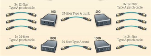
Connectivity Method A: In this connectivity method, a type-A trunk cable is used to connect a polarity A MTP cassette with key-up to key-down MTP adapters on each side of the link, then there is a A-to-B type duplex patch cable on the left and a A-to-A type duplex patch cable on the right as shown below.

method-a

Note: 1. Type-A trunk cable is a straight through cable with a key-up MTP connector on one end and a key-down MTP connector on the other end, which makes the fibers at each end of the cable have the same fiber position. For example, the fiber located at position 1 of the connector on one side will arrive at position 1 at the other connector. 2. A-to-A and A-to-B type patch cables are defined by TIA standard, which are terminated with LC or SC connectors to complete an end-to-end fiber duplex connection. Generally, A-to-A type patch cable is a cross version and A-to-B type is a straight version.

Connectivity Method B: In method B, a type-B trunk cable is used to connect a polarity B MTP cassette with key-up to key-up MTP adapters on each side of the link, and there are A-to-B type duplex patch cable used on both ends to achieve the connection between MTP cassettes and other equipment as shown below.

method-b

Note: Type-B trunk cable is with two key-up MTP connectors terminated at both ends. So the position 1 of one connector is corresponding to the position 12 of the other connector.

Connectivity Method C: In this method, a type-C trunk cable is used to connector a polarity A MTP cassettes on each side of the link, and then use two standard A-to-B type duplex cables at both ends of the link as shown below.

method-c

Note: Type-C trunk cable is similar to type-A trunk cable with one key-up connector and one key-down connector at each end, but in type-C cable, each adjacent pair of fibers at one end is flipped at the other end. For example, the fiber at position 1 on one connector is shifted to position 2 at the other connector, and the fiber at position 2 at one connector is shifted to the position 1 at the other connector, etc.

Conclusion
MTP cassette allows for rapid deployment of high density data center infrastructure as well as improved troubleshooting and reconfiguration during MACs(moves, adds and changes). The text above have introduced connectivity of polarity A and polarity B cassettes in three different connectivity method. We have to figure it out that its deployment is closely related to the other components used in the same method, when deploy it, you should pay much attention to the trunk cable and patch cable type used in different method.

2017年3月9日星期四

Two Simplest Ways to Get 40G to 40G Connection

Technologies revolving around virtualization, cloud computing and big data are requiring more throughput capabilities than ever before, and 10G Ethernet is just not enough to deliver these resources. This is where administrators may run into the challenge of upgrading from 10G to 40G and beyond. This post will introduce how to get 40G to 40G connection through two simplest ways: MTP trunk cable and QSFP+ DAC.

MTP Trunk Cable and QSFP+ DAC Overview
Terminated with MTP fiber connector at both ends, MTP trunk cable is used to connect MTP port modules for high density backbone cabling in data centers and other high dense degree environments. 12-fiber and 24-fiber MTP trunk cables are commonly used in networking applications: 12-fiber MTP trunk cable is normally for 40G Ethernet network, while 24-fiber MTP trunk cable is normally for 100G Ethernet network as shown below.

12-fiber and 24-fiber MTP trunk cable for 40G Ethernet

QSFP+ DAC as shown below is a copper 40GBase twinax cable that comes in either active or passive twinax cable assembly and connects directly into QSFP+ modules, which are permanently attached to both ends of the cable. These QSFP+ connectors are not real modules, since they are without expensive optical lasers. That’s why QSFP+ DAC cables are much more cheaper than fiber optic cables.

QSFP+ DAC

40G to 40G Connection With MTP Trunk Cable
In this scenario, you can simply use 12-fiber MTP MPO trunk cable and 40GBase-SR4/40GBase-CSR4/40GBase-PLR4/40GBase-PLRL4 QSFP+ transceivers to accomplish a quick connection between two 40G switches as shown below. 40GBase-SR4 and 40GBase-CSR4 are used for 40G transmission in short distances up to 150 m or 400 m over OM4 fibers, respectively. The 40GBase-PLRL4 and 40GBase-PLR4 can support transmission distance over single-mode fiber up to 1.4 km and 10 km respectively. All of these QSFP+ modules can deliver 40G over 4 lanes fibers at 10Gbps per lane. When they deployed with a 12-fiber MTP trunk cable, only 8 fibers will be used (4 for transmit and 4 for receive), leaving the other 4 fibers unused. All these modules can be purchased from FS.COM, and you can choose the right one according to the distance between your two switches.

MTP-MPO-trunk-cables-in-40G-connectivity

40G to 40G Connection With QSFP+ DAC
QSFP+ DAC and QSFP+ AOC cables are recommended when the distance between the two 40G switches is very short, normally 10 meters. Unlike the first solution, in this scenario, no QSFP+ modules are required. We just need to plug the QSFP+ connectors into the two QSFP+ interfaced switches within the same racks or across adjacent racks as shown below, and it can work, which is more easy to handle, especially for someone who is new to 40G deployment. FS.COM also provides QSFP+ DAC in active or passive versions (active for link length up to 7, 10 meters, and passive for 1, 3, 5 meters). You can choose the proper one up to your requirement.

40G to 40G connection with QSFP+ DAC

Conclusion
Data center migration to 40G Ethernet is imperative. If you are familiar with network deployment, and has bright budget, you can choose MTP trunk cable to get the 40G connection. If you are a new to 40G, you’d better choose 40G QSFP+ DAC for easy installation and lower investment. Of course, this is just personal suggestion, you can choose the right one according to your practical application.

2017年3月7日星期二

Can We Use Base-8 and Base-12 Together?

Although 10 Gigabit Ethernet is still marketing its way into the data centers, the need for faster data transfer rates is relentless, which means the migration to 40 Gigabit Ethernet is becoming inescapably compelling. For 40G Ethernet network, there are mainly two connectivity methods, one is Base-8, and the other is Base-12. Base-12 connectivity has had its place in the data center, while Base-8 is a new connectivity that could gain widespread acceptance in the next few years. With these two methods existing in 40G Ethernet network, there comes problems: Which one is more suitable for 40G network, or can we both use these two methods in 40G network? Read this articles, and you will get the detailed answers.

Base-12 Dominates the Market
Base-2 connectivity is the most commonly used one in the past, but as the data center grew to thousands of fiber ports engaged, stringing two-fiber patch cords across all corners of the data center will result in an unmanageable, and unreliable mess. So Base-12 connectivity is introduced. It is designed to develop a modular, high density, structured cabling system which could be deployed in data centers quickly, while also maximizing port densities within the rack space. In this connectivity method, all the fiber optic cables are based on an increment of 12 fiber, like 12-fiber or 24-fiber MTP trunk cable.

Base-12 system using a 24-fiber trunk cable

Base-8 Shines the Light
Base-12 connectivity is common in data center, but here comes a problem when installed it in a parallel system. For example, if we need to use 40GBase-SR4 optics implemented in a 12-fiber infrastructure, four fibers for transmit, and four fibers for receive, leaving four fibers unused per connection, this will lead to a significant and costly loss in fiber network utilization. But Base-8 can be a more cost-effective option for end-to-end MPO to MPO channels and architectures. With 8-fiber infrastructure, the 40GBase-SR4 module will use all the 8 fibers. Base-8 connectivity makes use of fiber links in increment of 8 versus 12. The 12-fiber trunk cables are replaced with trunk cables in increment of 8: 8-fiber, 16-fiber, or 24-fiber trunk cables, etc.

Base-8 system using a 24-fiber trunk cable

Can We Use Base-8 and Base-12 Together?
Although using Base-8 connectivity could decrease fiber consuming in supporting 40G data rates, in fact, in many cases, Base-8 connectivity isn’t a universal solution, and Base-12 may still be more cost-effective. So is it possible to have both Base-8 and Base-12 connectivity in the same data center? The answer could be “Yes” or “No”.

Base-8 and Base-12 Fiber Links Cannot Be Mixed and Matched
It is never possible to directly mix the components of Base-8 and Base-12 connectivity, or plug a Base-8 trunk into a 12-fiber module. Because a Base-12 trunk cable normally has unpinned MTP connector on both ends, and requires the use of pinned 12-fiber breakout modules, while a Base-8 trunk cable is manufactured with pinned MTP connectors at both ends (pinned and unpinned MTP connectors are shown below). So if we plug a Base-8 trunk into a 12-fiber breakout module, just like trying to mate two pinned connectors together, this connection will definitely not work, and vice verse.

pinned and unpinned MTP connector

Base-8 and Base-12 Can be Maintained in the Same Data Center Separately
It is possible to deploy both Base-8 and Base-12 connectivity within the same data center, just as long as the links are separate. Since Base-8 and Base-12 components are not interchangeable, during managing the data center physical layer infrastructure, we should do careful management and labeling practice to ensure we will not mix or mismatch them.

Conclusion
Base-12 connectivity has dominated the 40G network market for years, while the Base-8 connectivity is an additional option in the network designer’s tool kit to ensure that data centers have the most cost-effective, future-proof network available. When using Base-8 and Base-12 in network, make sure that you need to carefully manage and label them, and that the components in Base-8 and Base-12 won’t be mixed.