2017年4月24日星期一

100G QSFP28 and CFP Transceiver Cabling Solutions

By the end of 2016, 100G Ethernet has been widely deployed and becomes a significant portion in data center. Many network-equipment developers are motivated to introduce 100G devices like CFP and QSFP28 modules that consumes as little real estate and power as possible, while achieving necessary price points and delivering superior performance. This post is heading to talk about these two 100G modules and their cabling solutions.

CFP: Out With the Old
Specified by MSA among competing manufacturers, CFP is the first generation 100G transceiver which is designed after the SFP interface, but is significantly larger to support 100Gbps. As we all know, the original CFP has very large size, and in order to meet the need for higher performance and higher density in data center, there is the development of CFP2 and CFP4 specification, which specify a form-factor of 1/2 and 1/4 respectively in size of the original specification. Commonly used CFP/CFP2/CFP4 transceivers are available in 100GBase-SR10 and 100GBase-LR4.

100GBase-SR10 and 100GBase-LR4 CFP

QSFP28: In With the New
QSFP28 is the latest 100G form factor, which is a high-density, high-speed product solution designed for applications in the telecommunications, data center and networking markets. It utilizes four channels of respective signals with data rates up to 25Gbps to meet 100Gbps Ethernet requirement. 100GBase-SR4 and 100GBase-LR4 are two main types of QSFP28 module. The detailed specifications of these two QSFP28s are shown in the following table.

100GBase-SR4 and 100GBase-LR4 QSFP28

100GBase-SR10 Cabling Solution
100GBase-SR10 CFP uses a 24 strand MPO cable for connectivity (10 Tx and 10 Rx with each lane providing 10Gbps, leaving 4 channels unused). It can support maximum link length up to 100m and 150m respectively on OM3 and OM4 fiber cable. 100GBase-SR10 can also be used in 10x10 Gigabit Ethernet modes along with ribbon to duplex fiber breakout cables for connectivity to ten 10GBase-SR optical interface.

100GBase-SR10 CFP Cabling Solution

100GBase-SR4 Cabling Solution
Like 100GBase-SR10, 100GBase-SR4 QSFP28 also uses laser optimized OM3 and OM4 multimode fiber for indication. But 100GBase-SR4 QSFP28 utilizes 12f MPO trunk cable for connectivity (4 Tx and 4 Rx, leaving the middle four unused), which makes it possible to reuse 40GBase-SR4 fiber assemblies when upgrade from 40G to 100G.

100GBase-SR4 QSFP28 Cabling Solution

100GBase-LR4 Cabling Solution
Both 100GBase-LR4 CFP and QSFP28 are both interfaced with LC connector. They uses WDM technologies to achieve 100G transmission over single-mode duplex LC fiber patch cable supporting the link length up to 10km.

100GBase-LR4 Cabling Solution

Conclusion
As the need for high bandwidth is increasing, 100G Ethernet will widespread in data center quickly. Equipped with this basic information about 100G modules and their cabling solutions, we will have little worry upgrading to 100G Ethernet.
2017年4月21日星期五

QSFP28 and CFP Transceiver Cabling Solutions

By the end of 2016, 100G Ethernet has been widely deployed and becomes a significant portion in data center. Many network-equipment developers are motivated to introduce 100G devices like CFP and QSFP28 modules that consumes as little real estate and power as possible, while achieving necessary price points and delivering superior performance. This post is heading to talk about these two 100G modules and their cabling solutions.

CFP: Out With the Old
Specified by MSA among competing manufacturers, CFP is the first generation 100G transceiver which is designed after the SFP interface, but is significantly larger to support 100Gbps. As we all know, the original CFP has very large size, and in order to meet the need for higher performance and higher density in data center, there is the development of CFP2 and CFP4 specification, which specify a form-factor of 1/2 and 1/4 respectively in size of the original specification. Commonly used CFP/CFP2/CFP4 transceivers are available in 100GBase-SR10 and 100GBase-LR4.

100GBase-SR10 and 100GBase-LR4 CFP

QSFP28: In With the New
QSFP28 is the latest 100G form factor, which is a high-density, high-speed product solution designed for applications in the telecommunications, data center and networking markets. It utilizes four channels of respective signals with data rates up to 25Gbps to meet 100Gbps Ethernet requirement. 100GBase-SR4 and 100GBase-LR4 are two main types of QSFP28 module. The detailed specifications of these two QSFP28s are shown in the following table.

100GBase-SR4 and 100GBase-LR4 QSFP28

100GBase-SR10 Cabling Solution
100GBase-SR10 CFP uses a 24 strand MPO cable for connectivity (10 Tx and 10 Rx with each lane providing 10Gbps, leaving 4 channels unused). It can support maximum link length up to 100m and 150m respectively on OM3 and OM4 fiber cable. 100GBase-SR10 can also be used in 10x10 Gigabit Ethernet modes along with ribbon to duplex fiber breakout cables for connectivity to ten 10GBase-SR optical interface.

100GBase-SR10 CFP Cabling Solution

100GBase-SR4 Cabling Solution
Like 100GBase-SR10, 100GBase-SR4 QSFP28 also uses laser optimized OM3 and OM4 multimode fiber for indication. But 100GBase-SR4 QSFP28 utilizes 12f MPO trunk cable for connectivity (4 Tx and 4 Rx, leaving the middle four unused), which makes it possible to reuse 40GBase-SR4 fiber assemblies when upgrade from 40G to 100G.

100GBase-SR4 QSFP28 Cabling Solution

100GBase-LR4 Cabling Solution
Both 100GBase-LR4 CFP and QSFP28 are both interfaced with LC connector. They uses WDM technologies to achieve 100G transmission over single-mode duplex LC fiber patch cable supporting the link length up to 10km.

100GBase-LR4 Cabling Solution

Conclusion
As the need for high bandwidth is increasing, 100G Ethernet will widespread in data center quickly. Equipped with this basic information about 100G modules and their cabling solutions, we will have little worry upgrading to 100G Ethernet.
2017年4月17日星期一

Decoding Four types of 100G QSFP28 Transceiver

With the development of IP-based multimedia service, especially video service, network traffic has been continuously rising. As a result, 40G and 100G have emerged as the key technologies capable of supporting the growth in network bandwidth. After a lengthy period of hype, 40G technologies have finally widely been deployed. And now it is 100G’s turn. While 100G networking may seem excessive to many right now, there are many industries where that 100G speeds are quickly becoming necessary. This post will introduce four QSFP28 transceiver types that are commonly used in 100G data center.

QSFP-100G-SR4
QSFP-100G-SR4 or 100GBase-SR4 QSFP28 optical transceiver is a full duplex, photonic-integrated 100G module, which uses 4 fibers for transmit and 4 for receive, with each lane supporting 25Gbp, providing an aggregated data rate of 100Ggps as shown below on up to 70m of OM3 MMF and to 100m of OM4 MMF. Like 40GBase-SR4, 100Gbase-SR4 uses a MPO 12 cable with 4 strand for transmit and 4 for receive, allowing for existing 40GBase-SR4 fiber assemblies to be reused when higher performance is needed. This interface standard has been introduced alongside the 100G QSFP28 offerings now, arriving on the market in order to make any 40GbE to 100GbE upgrade as seamless as possible.

QSFP28 sr4

QSFP-100G-LR4
QSFP-100G-LR or 100GBase-LR4 QSFP28 is another 100G standard, which focuses on longer data transmission up to 10km over single-mode fiber. Like 40GBase-LR4, the 100GBase-LR4 is also a multilane optic. However, each lane’s data rate is increased to 25Gbps. It has duplex LC interface and uses WDM technologies to achieve 100G dual-way transmission over four different wavelengths around 1310nm that can be seen in the image below.

qsfp28 lr4

QSFP-100G-PSM4
Targeted to service the need on a parallel single-mode infrastructure, QSFP28 PSM4 module is a low cost solution to long reach data center interconnect. It uses four parallel fibers (lanes) operating in each direction, with each lane carrying a 25G optical transmission as shown below. Interfaced with MPO connector, it can support distance up to 500 meters over single-mode fiber, which covers a wide rage of applications in data center.

qsfp28 psm4

QSFP-100G-CWDM4
Backed by the CWDM4 MSA Group, QSFP28 CWDM4 is a 100G interface that address data communication links up to 2km in the data center. The CWDM4 architecture employs 4 lanes of 25Gbps using CWDM technology to transport 100G optical traffic across duplex LC single-mode fiber. Compared to 100GBase-LR4, CWDM4 is an alternative for long transmission distance in data center. The working principle can be seen in the following image.

qsfp28 cwdm4

Summary
100G Ethernet is no longer a fantasy, and it is on the way. QSFP28 is a key to the 100G deployment. In the part above, we have introduced four types QSFP28 modules widely used in 100G network. All of these modules that have been tested and are 100% compatible can be purchased in FS.COM. If you have any related requirement, kindly visit FS.COM.

2017年4月11日星期二

Applications of MTP Conversion Harness Cable

As we all know, Base-8, Base-12 and Base-24 are three mainstream MTP backbones widely used for higher speed 40/100G data centers. Many of today’s legacy infrastructures are using a Base-12 MTP backbone design, however, experience shows us that this connector is not very suitable for higher rate switches or servers. And at present, base-8 is the preferred connector for 40G (SR4) transceivers, while Base-24 is often chosen for 100G transceivers (SR10). How could we convert the previously built Base-12 backbone to the currently popular Base-8 and Base-24 backbones, or how to migrate from 40G Base-8 backbone to 100G Base-24 backbone? There comes a solution—MTP conversion harness cable. MTP conversion cable is a type of MTP harness cable, allowing users to convert their existing MTP backbone cables to an MTP type which matches their active equipment. There are mainly three types of MTP conversion cables: Base-8 conversion harness, Base-12 conversion harness and Base-24 conversion harness. The following text will mainly introduce these three conversion cable types’ applications.

Base-8 Conversion Harness
Base-8 conversion harness , also referred to as 1x3 MTP conversion cable, is terminated with three Base-8 connectors at one end and one Base-24 connector at the other end. Three Base-8 connectors are combined inside the furcation housing, so that the single 24-fiber MTP connector can be plugged into the transceiver as shown in the image below. This conversion cable type allows users to convert their existing Base-8 MTP backbone trunks into a single 24 fiber MTP connector for use in SR10 (100G) deployment.

Base-8 Conversion Harness

Base-12 Conversion Harness
There are two types of Base-12 conversion harness—2x3 MTP conversion cable and 2x1 MTP conversion cable shown in the following image. 2x3 MTP conversion cable, consisted of two Base-12 connectors combined inside the housing to produce three Base-8 connection at the other end of the assembly, is often used to convert pre-installed 12-fiber backbone trunks into Base-8 connections, so that 40G data rates can be achieved. 2x1 conversion cable is attached with two 12-fiber MTP connectors at one end and a single 24-fiber connector at the other end. This type of Base-12 conversion harnessallows users to convert the 12-fiber MTP backbone trunks into Base-24 connections for achieving 100G data rates.

2x1 MTP Harness Conversion Cable
2x3-MTP-conversion-cable

Base-24 Conversion Harness
Base-24 conversion harness is exactly the same harness as Base-8 conversion cable, but it is used to convert a Base-24 connector into 3xBase-8 connectors in the backbone based on Base-24 design. A single Base-24 connection is split into three Base-8 connections providing users with three 40G ports as shown in the picture below.

Base-24 MTP Harness Conversion

Conclusion
MTP conversion harness cable provides a flexible solution for the conversion from existing Base-12 backbones to popular Base-8 and Base-24 connections, and it is also a cost-effective solution for the conversion between 40G and 100G. The features and usages of three MTP conversion cable types have been introduced above. According to your practical application, you can choose the most suitable one.

2017年4月7日星期五

Why Choose Base-8 MTP Link for Future-Proofing Your Network?

When deploying a new fiber system, data center managers will always consider whether the system can be easily upgraded to higher data rate network or not in the future, since network reconfiguration will cost much time and money. So choosing a right fiber optic link is the very step to ensure an efficient, future-proof data center. Here, we highly recommend Base-8 MTP link for your home network or data center. Why? Please continue reading the following text.

More Flexible
As we all know, 40G and 100G applications prefer to use parallel SR4 optics (four fiber for transmitting and four fiber for receiving) to transmit data rates. Base-8 connectivity makes use of fiber links in increment of 8 versus 12 or 24, which can allow customers to patch directly to SR4 transceivers without having to convert connectors with different counts or waste fibers in the backbone. Therefore, if customers who still run 10G data rates deploy Base-8 MTP link at the very beginning could migrate to 40G, 100G or beyond without changing the current fiber link, which is more flexible and easy.

High Investment but High Return
Actually, compared to Base-12 and Base-24 backbones, Base-8 link requires higher investment, since more MTP connectors will be installed from the start. However, as we have mentioned above, Base-8 is the most suitable solution for SR4 applications which means that if managers plan to upgrade to higher speed 40/100G network, no additional conversion cable or conversion modules will be needed, bringing a higher return in the future.

100% Fiber Utilization
In most 40/100G cases, Base-12 backbones are more recommended to use between core switched and the equipment distribution area in the data center, but actually, there is no standardized transceiver using all 12 fibers in a Base-12 MTP connector. Besides, with more and more data center managers prefer to use SR4 interface in 40G and 100G applications, using Base-8 link can achieve 100% fiber utilization. So do you still insist on deploying Base-12 today and risk wasting 33% of backbone fibers as shown in the image below tomorrow, or going straight with Base-8 knowing that it will be the best investment in the future?

12-fiber MPO for 40G transmission

Summary
When deploying a new fiber link, we should consider in the long term instead of in the short term. All the proof that we have talked above have indicates that Base-8 MTP link will be the best solution for future-proofing your network. With Base-8 MTP link today, we can easily upgrade to 40G or higher speed network tomorrow.

2017年4月5日星期三

100% Fiber Utilization with 2x3 MTP Conversion Cable

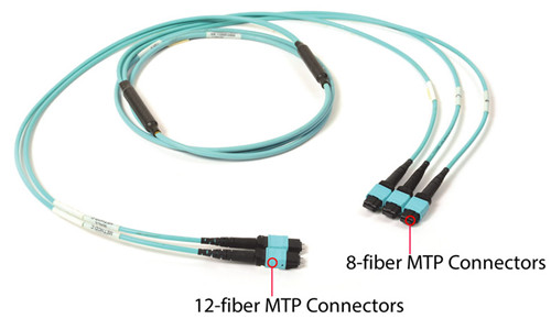
When faced with eight-fiber parallel applications, such as 40GBase-SR4 40 Gigabit Ethernet and 100GBase-SR4 100 Gigabit Ethernet, technicians who use conventional 12-fiber MTP cable will waste a third of the fibers in the cable plant (four fibers for transmitting and four fibers for receiving, leaving the middle four unused). To overcome this inefficiency, new 2x3 MTP conversion harness is introduced. 2x3 MTP conversion cable terminated with three 8-fiber MTP connectors on one end and two 12-fiber MTP connectors on the other end can convert the signal from three four-channel transceivers to two 12-fiber trunks, which means 100% utilization of a 12-fiber network. The following text will mainly talk about how 2x3 MTP conversion cable uses all the fibers in 10G to 40G and 40G to 40G connection.
2x3 MTP conversion cable
10G to 40G Connection With 2x3 MTP Conversion Cable
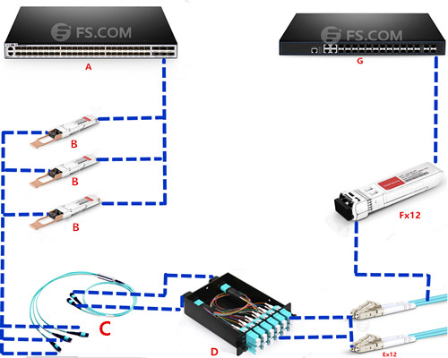
Although upgrading from 10G to 40G Ethernet becomes common in most data centers, it is still impossible to replace all the 10G devices with 40G devices for more cost consumption. There are many solutions that we have introduced in the previous articles used to connect 10G to 40G equipment. 2x3 MTP conversion cable is a cost-effective one. The scenario can be clearly see from the following image. The three 8-fiber MTP connectors terminated at the 2x3 MTP conversion cable are directly plugged into the three 40GBase-SR4 modules(100% fiber utilization), then all cable assemblies will be plugged into the QSFP+ interfaced switch. The conversion from 40G to 10G is the most important step in this connectivity. Here we may use MTP or MPO LC cassette (2x12MTP-12xLC cassette) to connect two 12-fiber MTP connectors at the other end of the conversion cable to twelve duplex LC patch cables. Then all the LC cable assemblies with 10GBase-SR modules will be directly plugged into the SFP+ port switch. The whole connection do not waste any fiber.
10G to 40G connection with 2x3 MTP conversion cable
IdentifierFS.COM ProductsDescription
AS5850-48S6Q48x 10GbE SFP+ with 6x 40GbE QSFP+ Switch
BQSFP-SR4-40GQSFP+ SR4 optics; 150m @ OM4 MMF, 100m@ OM3 MMF
C2x3 MTP Conversion Cable2xMTP to 3xMTP; 50/125μm MM (OM3)
D2x12MTP-12xLC cassetteMTP-12 to LC UPC Duplex 24 Fibers MPO/MTP Cassette, 10G OM3, Polarity A
EDuplex LC Patch CableDuplex LC; OM3
FSFP-10G-SRSFP SR optics; 300m over OM3 MMF
GS3800-24F4S20x 100/1000Base SFP with 4x 1GE Combo and 4x 10GE SFP+ Switch
40G to 40G Connection With 2x3 MTP Conversion Cable
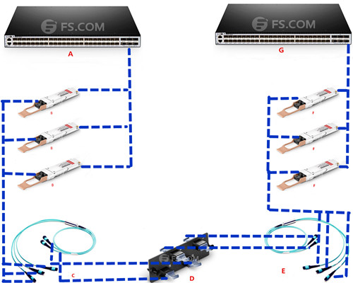
In this scenario, the three 8-fiber MTP connectors at the end of the conversion cable are directly plugged into the 40G module, then into 40G switch. In order to make sure all the fibers can be used in this 40G to 40G connectivity, we may use a adapter panel to connect the two 12-fiber MTP connectors of the conversion cable to the two 12-fiber MTP connectors attached at the end of the other 2x3 MTP conversion cable. Then the three 8-fiber MTP harness end with 40G modules will be plugged into the QSFP+ port switch. If you feel confused with my sentences, more clear description is shown in the image below.
40G to 40G connection with 2x3 MTP conversion cable
IdentifierFS.COM ProductsDescription
AS5850-48S6Q48x 10GbE SFP+ with 6x 40GbE QSFP+ Switch
BQSFP-SR4-40G QSFP+ SR4 optics; 150m @ OM4 MMF, 100m@ OM3 MMF
C2x3 MTP Conversion Cable2xMTP to 3xMTP; 50/125μm MM (OM3)
DMTP Adapter PanelFiber Adapter Panel with 4 MTP(12/24F) Key-up/Key-down Adapters
E2x3 MTP Conversion Cable2xMTP to 3xMTP; 50/125μm MM (OM3)
FQSFP-SR4-40GQSFP+ SR4 optics; 150m @ OM4 MMF, 100m@ OM3 MMF
GS5850-48S6Q48x 10GbE SFP+ with 6x 40GbE QSFP+ Switch
Conclusion
You can gain great value to deploy 2x3 MTP conversion cable, which does not add any connectivity to the link and it allows 100 percent fiber utilization and constitute the most commonly deployed method. However, you have to notice that the use of the 2x3 MTP conversion cable assembly at the core spine switch is not desirable, because patching across blades and chassis is a common practice.